Difference between revisions of "Steering Wheel"
(→Description) |
|||
| (24 intermediate revisions by 2 users not shown) | |||
| Line 1: | Line 1: | ||
| + | [[File:RIMG3067b.jpg|thumb]] | ||
| + | |||
== Description == | == Description == | ||
| − | + | Steering wheel for use with the [[C128|Commodore 128]], home-built in 1988. | |
| + | |||
| + | The steering wheel was taken from a wreck of an unidentified microcar found in the woods on the Belgian-German border around 1985. My best guess so far is that it was a [http://microcarmuseum.com/tour/goggo-t250sunroof.html Goggomobil T]. In any case, the wheel looks exactly like that one. There is no marking whatsoever. | ||
| − | + | Coincidently, the steering wheel has the same color beige as the [[C128]] itself. | |
| − | A ball-bearing was put on the wheel | + | A ball-bearing was put on the wheel axle to hold it in place in a wooden frame. The frame could then be fastened to a table with clamps. |
| − | Further down the | + | Further down the axle is a small wheel which drives a multi-turn potentiometer. The potentiometer is then connected to an ADC on one of the joystick ports of the Commodore. |
| − | + | To calibrate, the wheel can be slightly lifted to decouple it from the potentiometer. | |
| + | Sewing machine foot pedals can be used for the accelerator and break. The idea was to connect them to ADCs too but since the only software that was adapted (see below) had only a binary accelerator/break, the pedals were connected to the joystick up/down lines instead. | ||
== Condition == | == Condition == | ||
| − | The wooden frame is | + | The wooden frame is somewhat broken and fragile. Turning the wheel must be done with some care, which is not really the object of a racing game... |
| + | Apart from that, it is (again) in working condition. | ||
== Software == | == Software == | ||
| Line 21: | Line 27: | ||
Test Drive was adapted to make use of the steering wheel and accelerator pedal. | Test Drive was adapted to make use of the steering wheel and accelerator pedal. | ||
| − | + | I have made a fresh backup of the adapted Test Drive floppy, including d64 images. | |
| + | |||
| + | == TODO == | ||
| + | |||
| + | Attach a pedal to a joystick for the accelerator (port 2 UP). | ||
Latest revision as of 02:20, 29 July 2010
Contents
Description
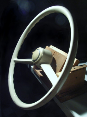
Steering wheel for use with the Commodore 128, home-built in 1988.
The steering wheel was taken from a wreck of an unidentified microcar found in the woods on the Belgian-German border around 1985. My best guess so far is that it was a Goggomobil T. In any case, the wheel looks exactly like that one. There is no marking whatsoever.
Coincidently, the steering wheel has the same color beige as the C128 itself.
A ball-bearing was put on the wheel axle to hold it in place in a wooden frame. The frame could then be fastened to a table with clamps.
Further down the axle is a small wheel which drives a multi-turn potentiometer. The potentiometer is then connected to an ADC on one of the joystick ports of the Commodore.
To calibrate, the wheel can be slightly lifted to decouple it from the potentiometer.
Sewing machine foot pedals can be used for the accelerator and break. The idea was to connect them to ADCs too but since the only software that was adapted (see below) had only a binary accelerator/break, the pedals were connected to the joystick up/down lines instead.
Condition
The wooden frame is somewhat broken and fragile. Turning the wheel must be done with some care, which is not really the object of a racing game...
Apart from that, it is (again) in working condition.
Software
Test Drive was adapted to make use of the steering wheel and accelerator pedal.
I have made a fresh backup of the adapted Test Drive floppy, including d64 images.
TODO
Attach a pedal to a joystick for the accelerator (port 2 UP).
